To reach the components concerned, the circuit boards need to be removed from the FH40T's housing.
To make removal possible, several wires need to be unsoldered.
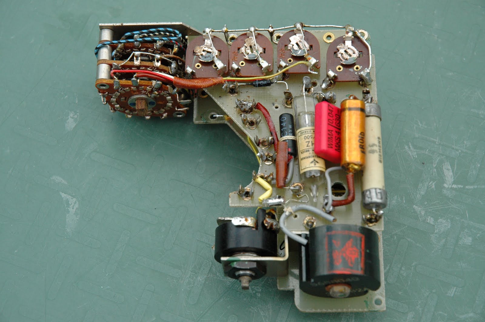
To document the situation, to be able to connect all wires after repair of the circuit, I took this series of pictures:


I've replaced all three 0.025µF / 400V capacitors, a 0.01µF / 250V capacitor and the three 100µF / 4V / 6V electrolytic caps (the meter averaging caps and supply filtering cap) too, as they probably have lost their capacity due to drying out.
After re-assembly of the unit, it seems to be working again, so the operation succeeded ! H.V. measured 500V at the FHZ55/500 stabilizer tube and it's glowing softly.
Thank you for the high quality images. To contribute a little, here is the circuit diagram:
ReplyDeletehttp://www.kronjaeger.com/hv-old/radio/geiger/schaltplan.jpg
Yours, katze
Hello
ReplyDeleteI see with pleasure that the "Probe Selection Guide" is useful:)
I hope to update the document ...
I also got on ebay an SI8B , I want to connect to a DOM410.
I'll try as soon as possible.
bye
Hello LABX,
ReplyDeleteyes I've found your "Probe Selection Guide" very useful. Thank you! Keep up the good work.
RG.
Hi
ReplyDeleteI updated the document.
I added other usual tables.
http://labx.altervista.org/100rad/100rad.htm
greetings